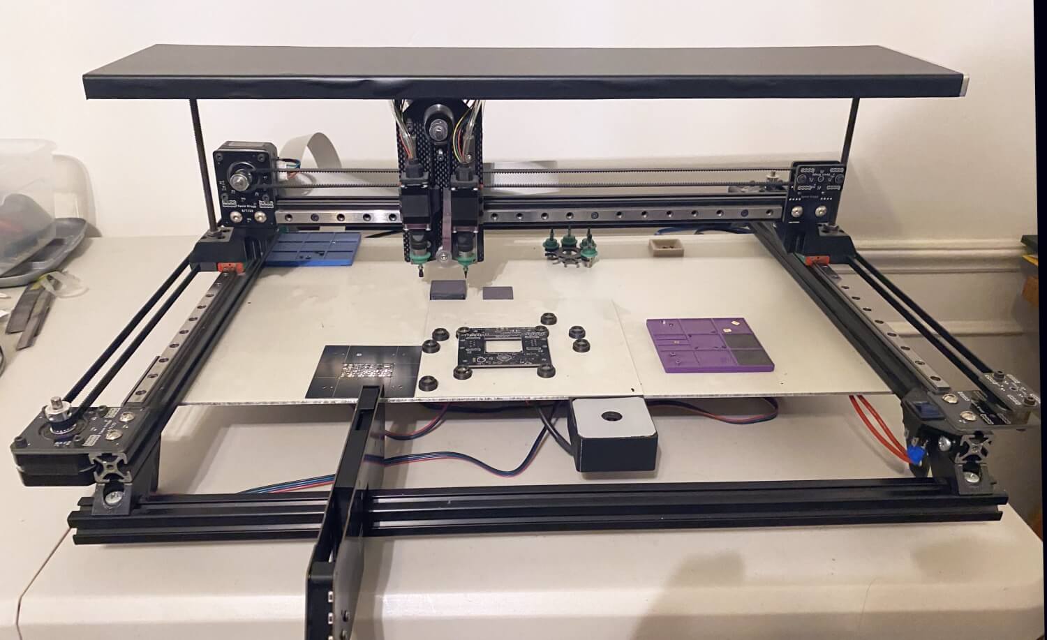
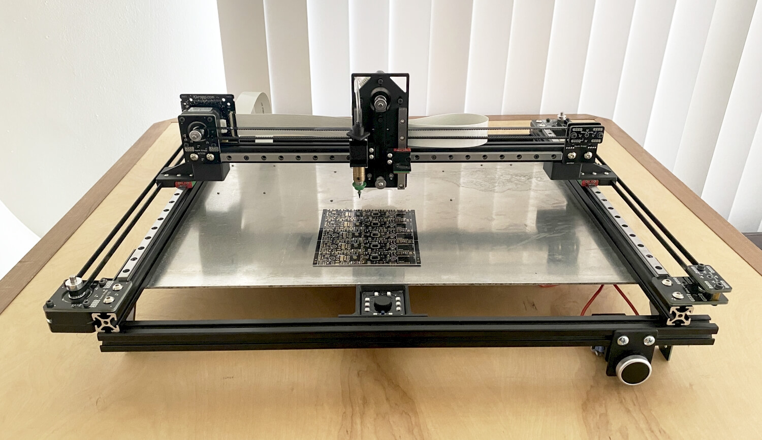
With the goal to make a medium run of PCBA’s and not wanting to outsource it I started to look at a pick and place machine for the home shop. It didn’t take long to realize I couldn’t afford to buy one or fit a conventional pick and place machine in my garage. I came across the opensouce openpnp and found a ton of user builds and information. I won’t go over the software so much as the hardware and differences from previous builds that have already been done. Initial inspiration came from a project called simple pnp a crowd funded project that seems to have stalled on the delivery to the funders. The main appeal from this design was the x and dual y axis linear drives and guides were 3 of the same assembly’s. I started with this as a base and tried to simplify it even more.
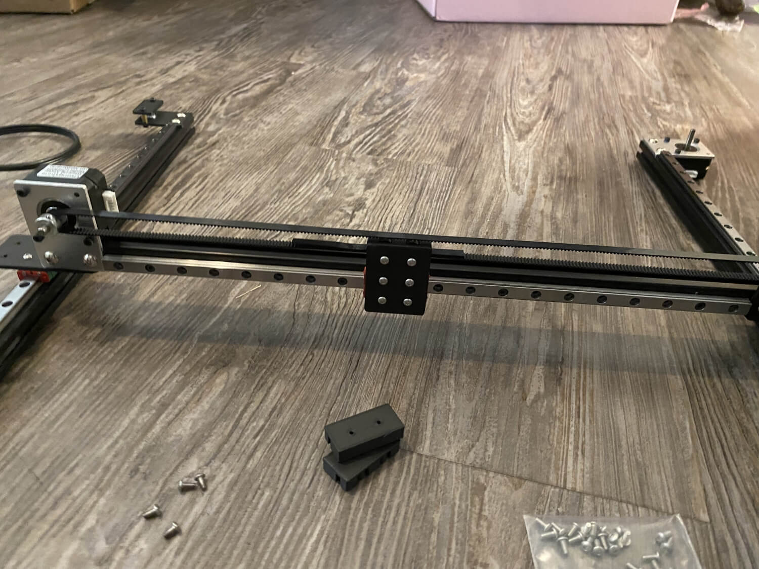
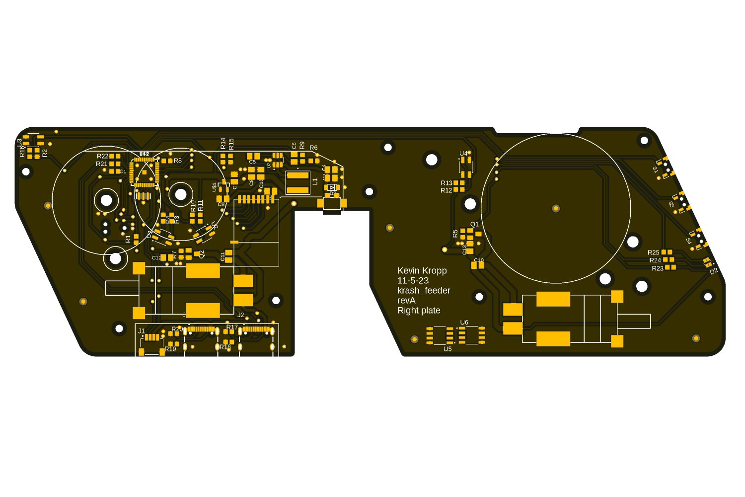
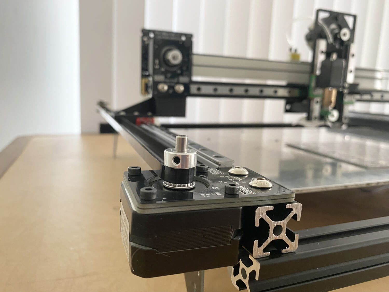
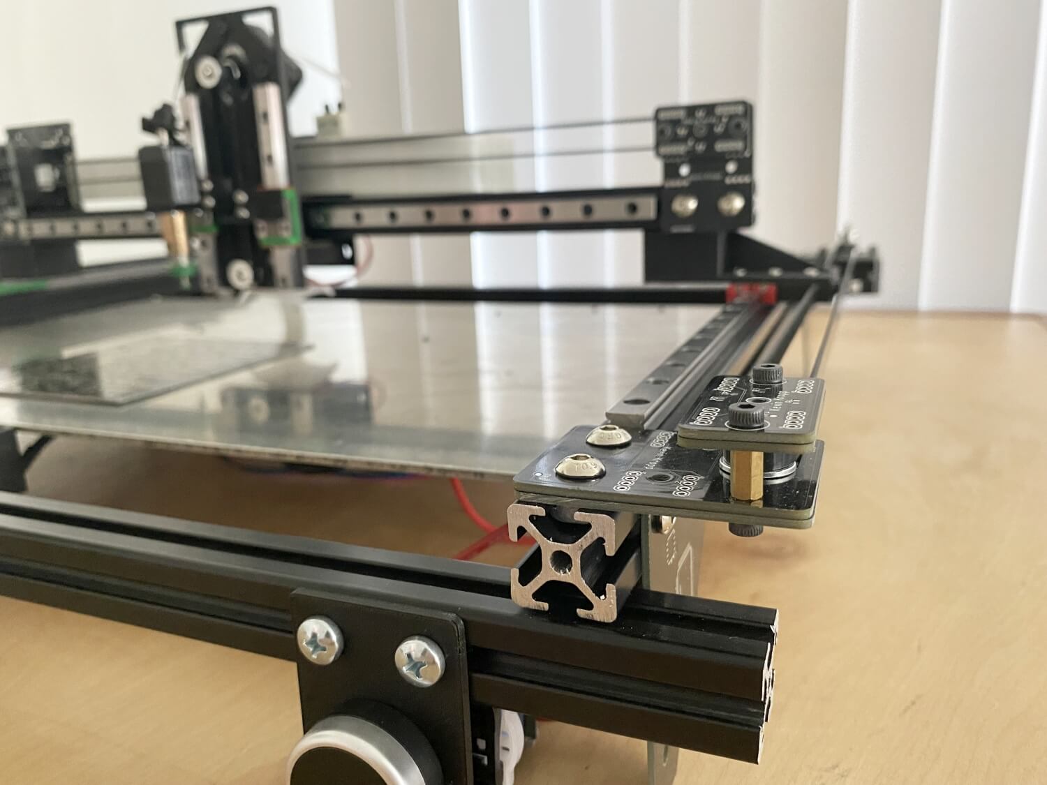
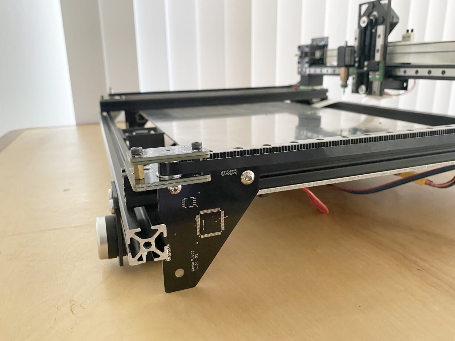
As opposed to using aluminum to mount the motors I made all the brackets that were plates out of pcbs so the motor mounts, pully mounts, feet, and even the head support is designed to be produced with PCB’s
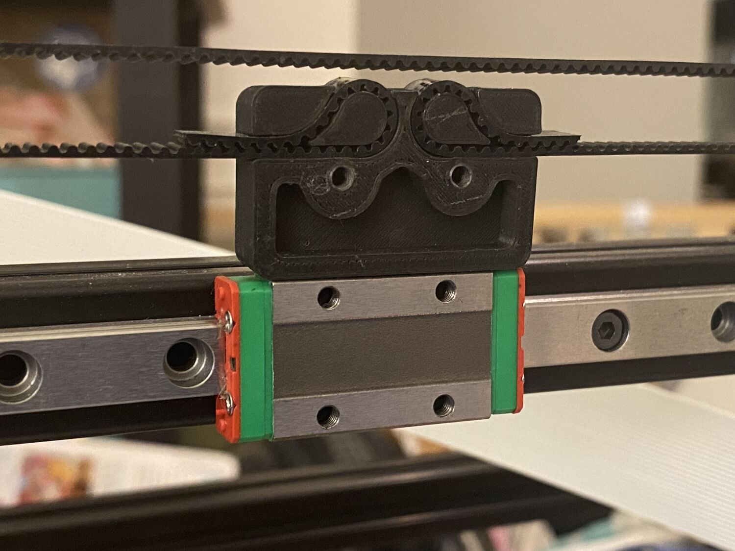
I used 3d printed parts for the rest of the brackets and belt connectors
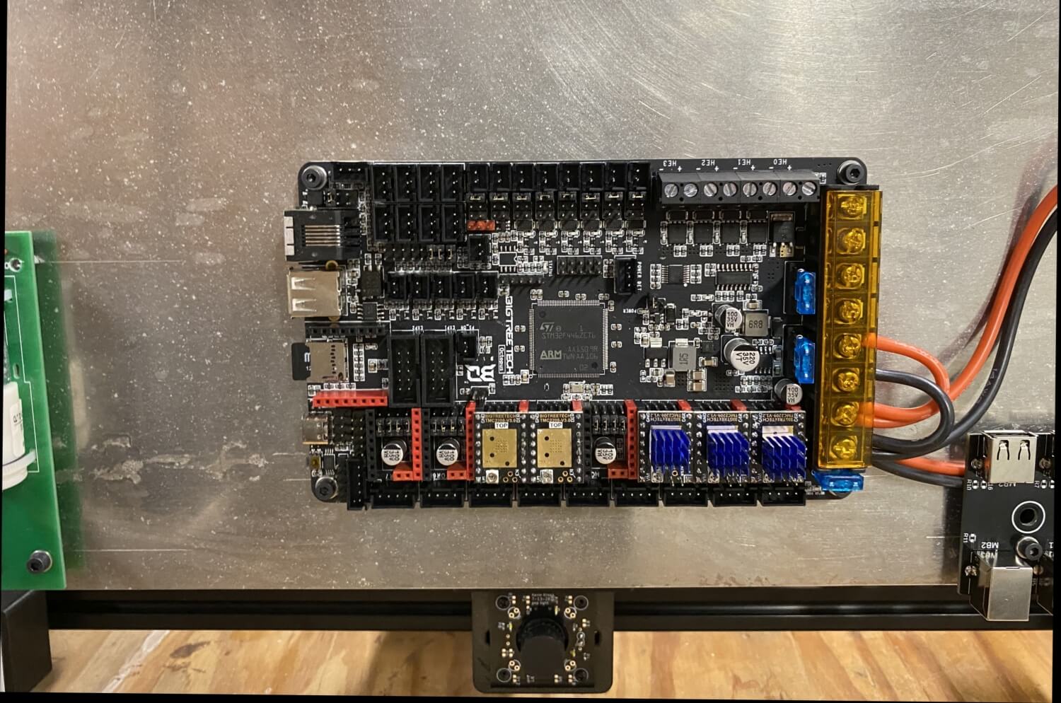
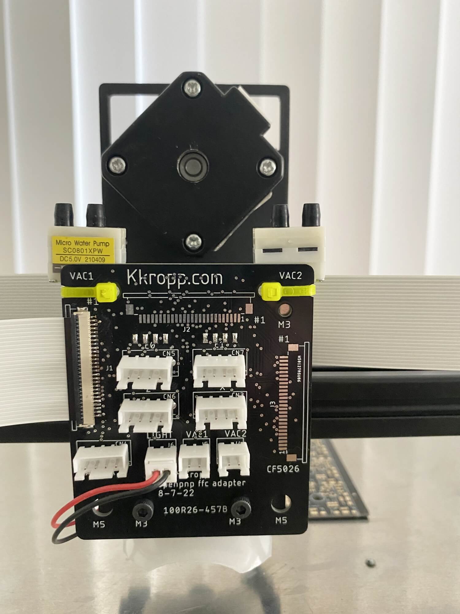
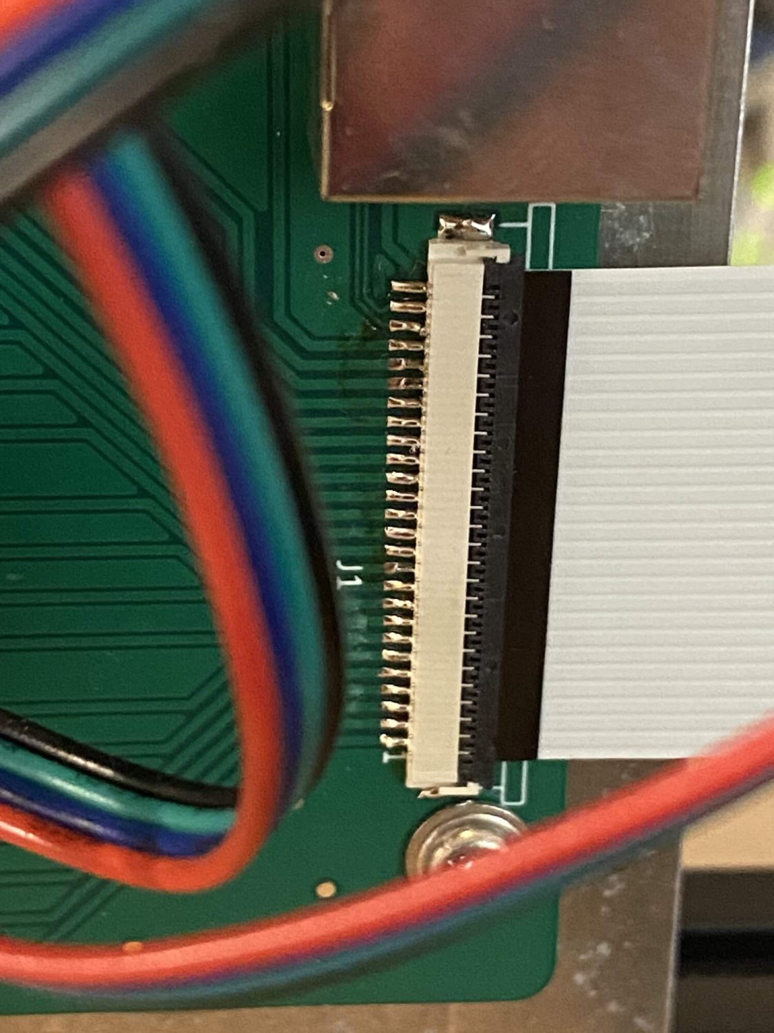
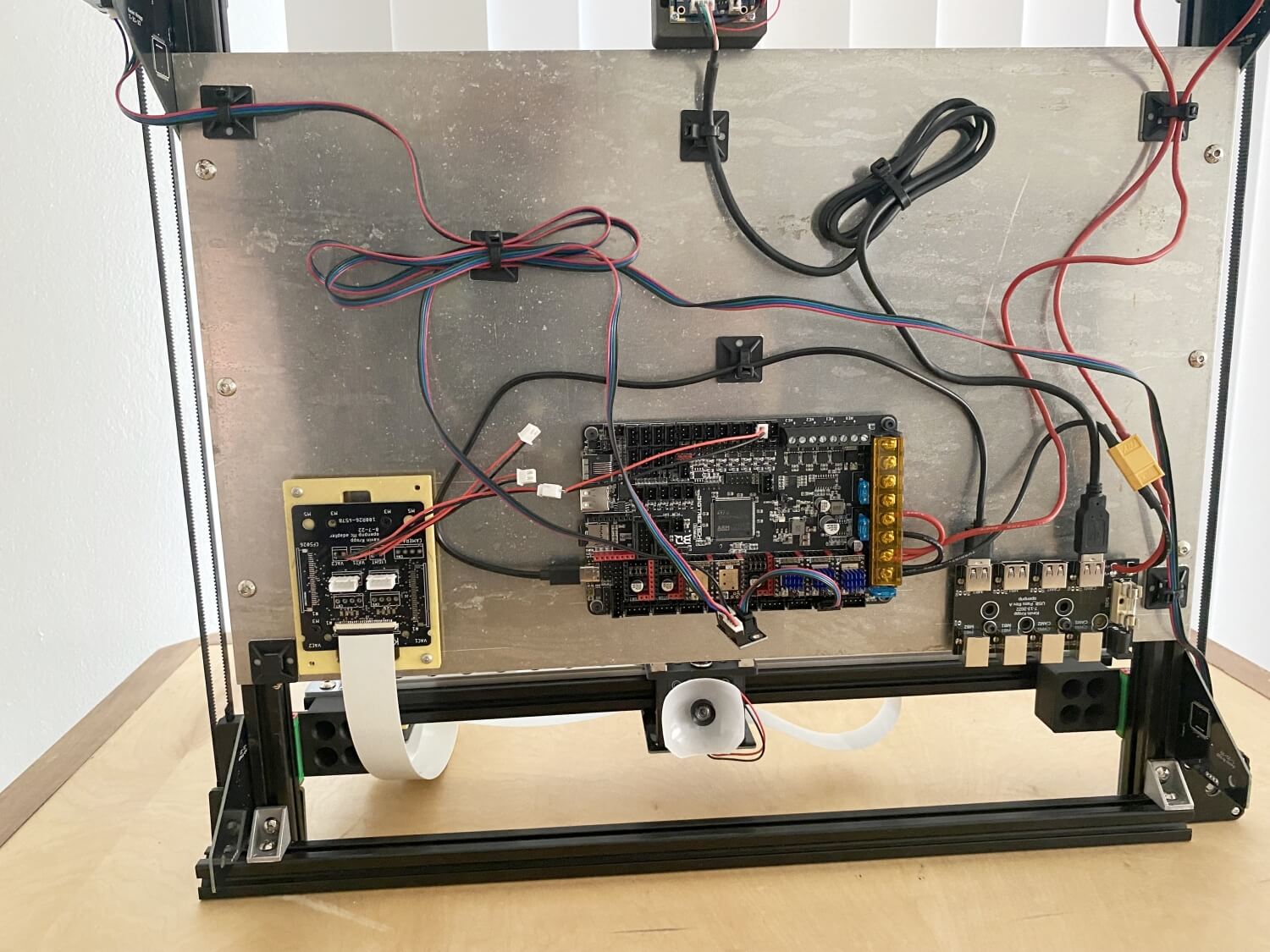
I used Flat flex cables to send and get data from the head as opposed to the more common wire loom in a drag chain. I wanted the head to be easy to connect and disconnect and was initially concered that the cables could not handle the current as the stated rating is only a few hunded mah per pin and the motors would pottailly draw 700-800mah. I tested a couple cables and was supprised to find I could sustain about 4A for a single pin and burst failure at 6A. this setup has a breakout board on the bottom with data going to the mainboard and a USB port for the camera connection on the head camera. it has a 18″ 20 pin FFC that goes up to another pcb near the x axis motor. a couple 4 or the pins breakout and go to the motor while the the other 16 go to another FFC to connect to the head.
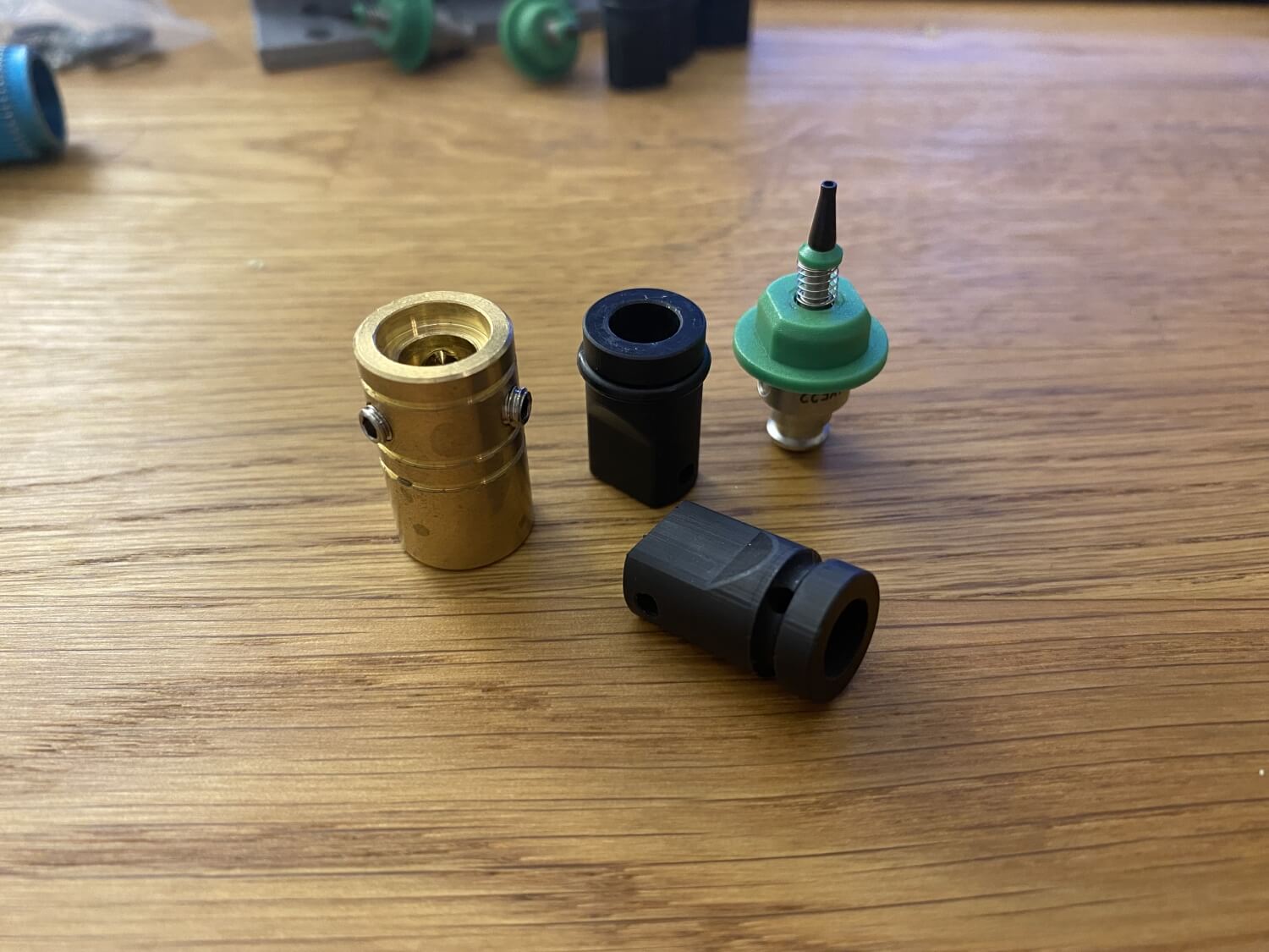
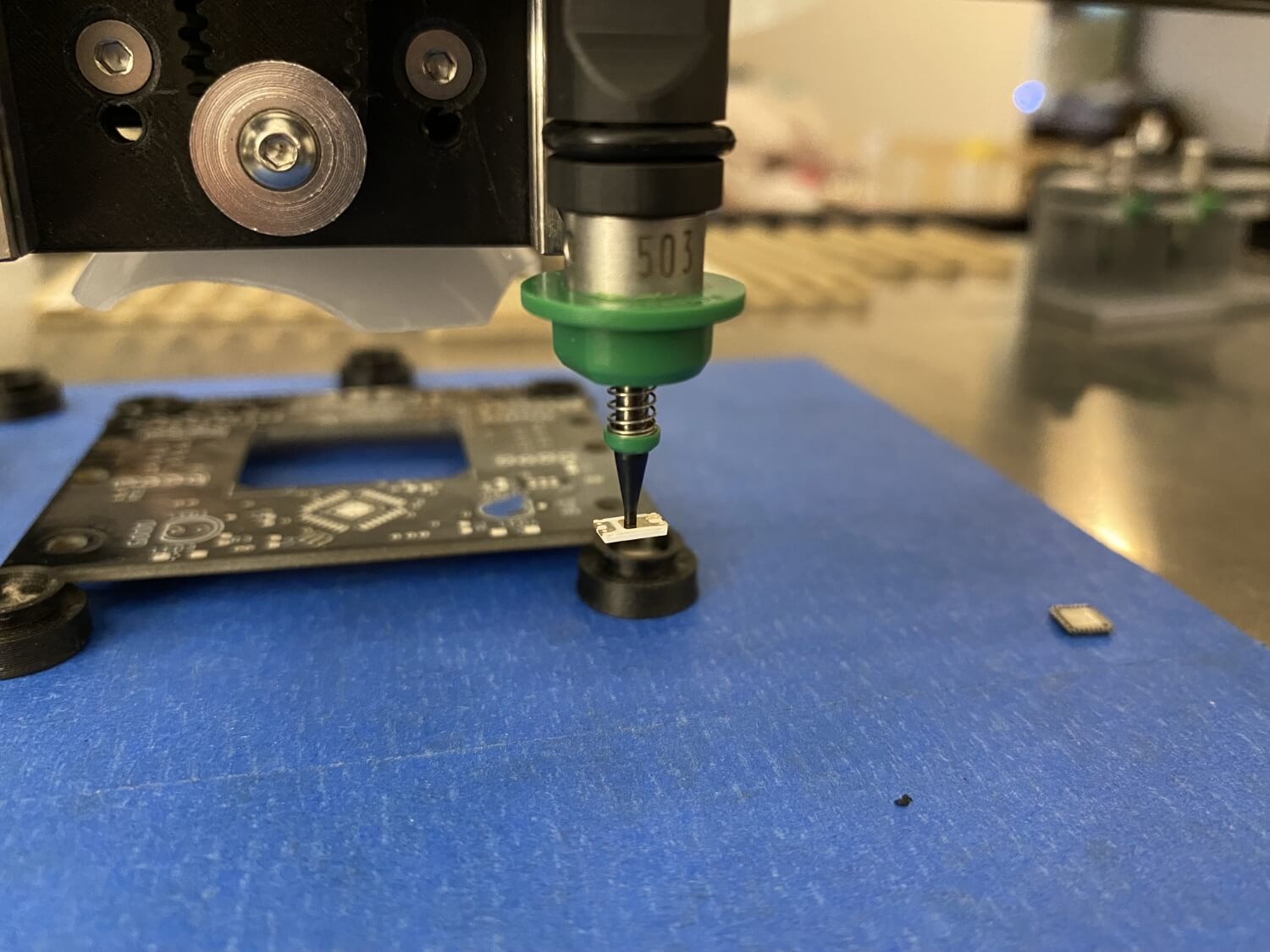
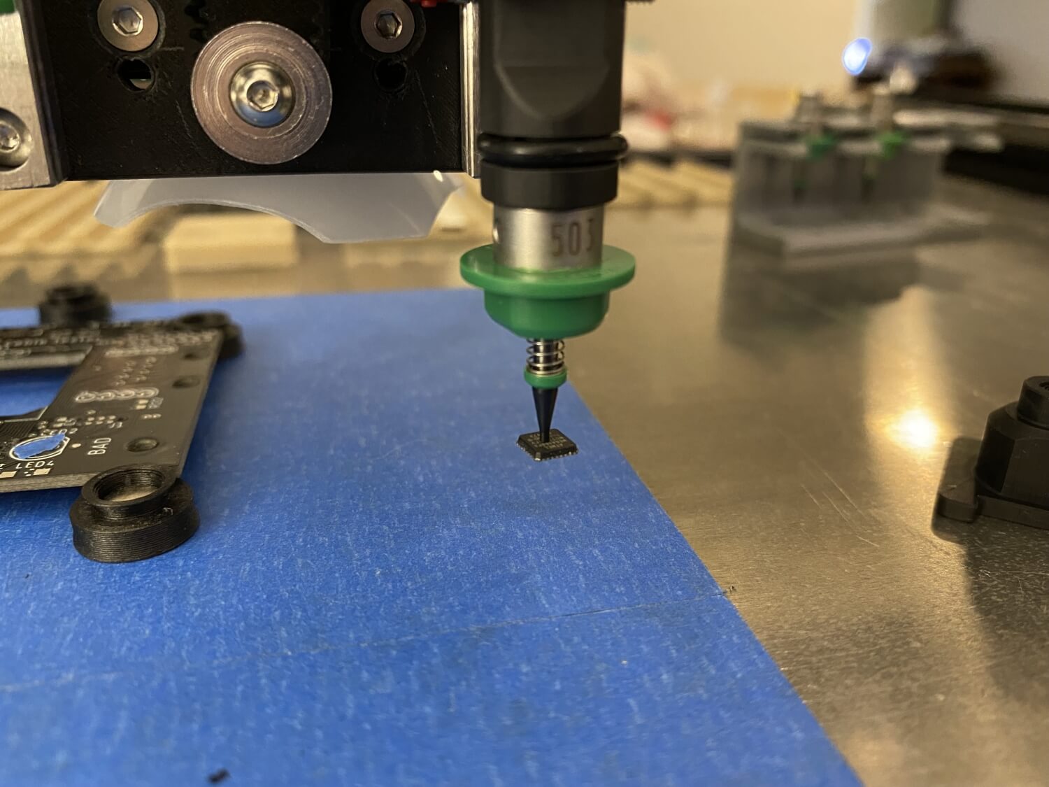
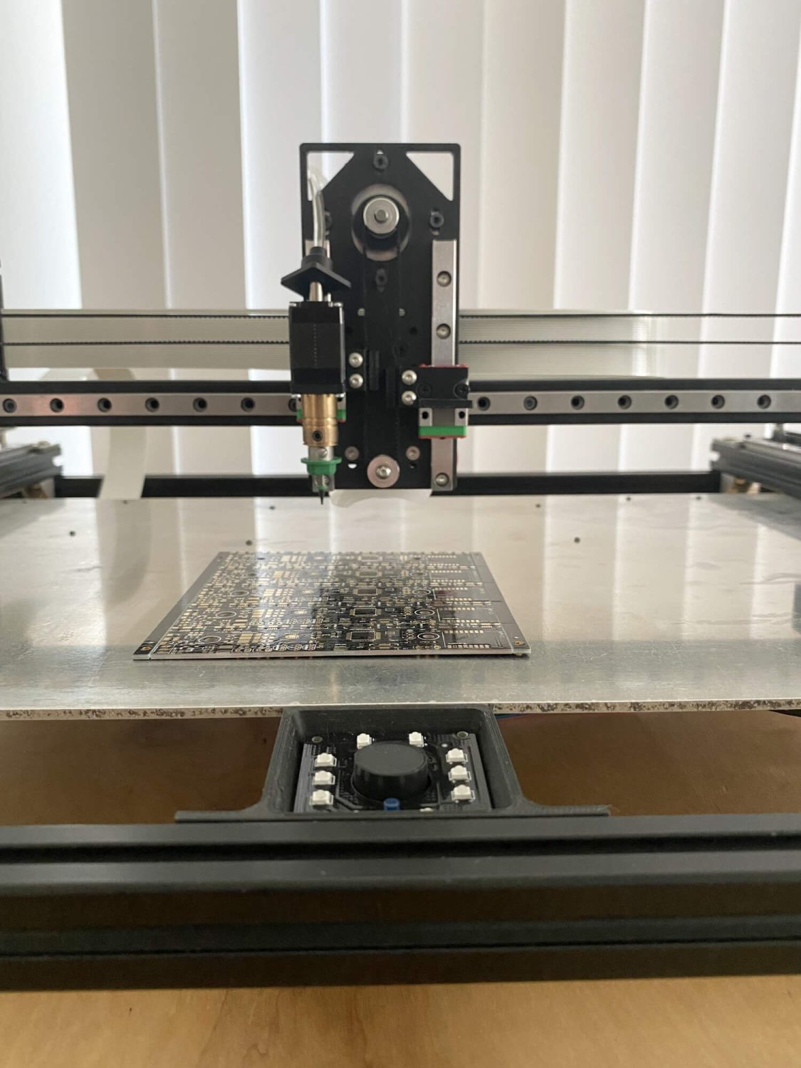
3d printed nozzle adapter. I resin printed these nozzle adapters and followed a popular online design where an o-ring hold ball detents in place. The online community seems to be in agreement that it would not be tight tolerance enough and seal well but apart from adjusting the dimensions for a press fit it has worked.
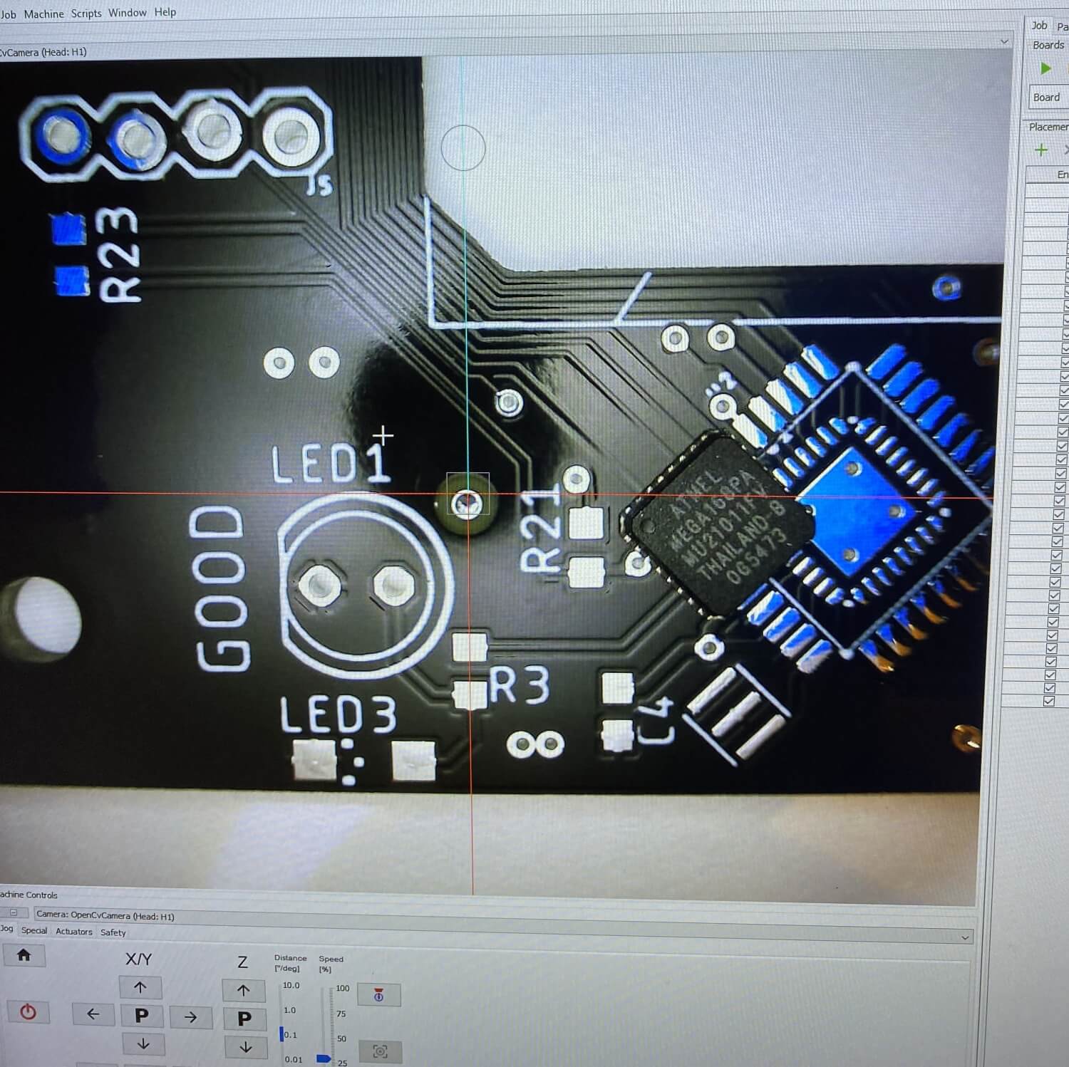
I also wanted to reduce wires wherever possible and opted for the tcm2130 drivers with stall guard and while they took quite a bit of configuration to setup they have been really reliable. I was initially concerned about the repeatability but the machine only uses the limit switches to rough calibrate location and will do a fine calibration with a fixed fiducial for most movements to confirm locations.
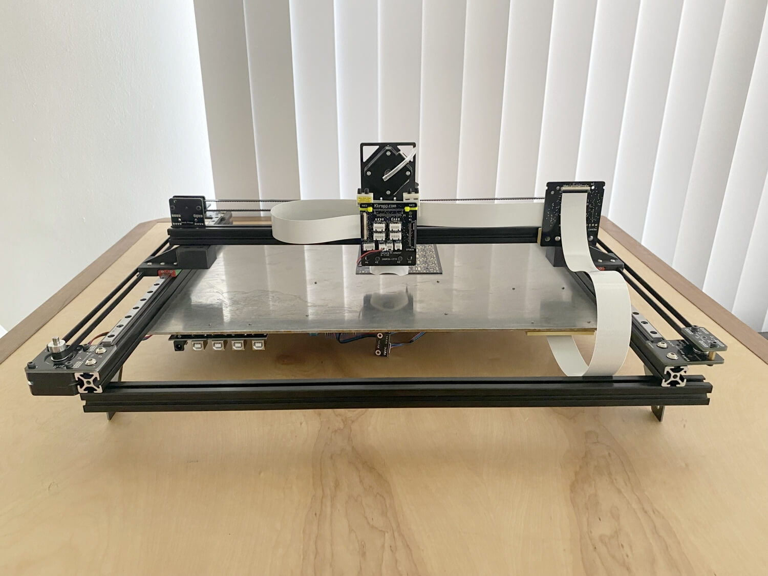
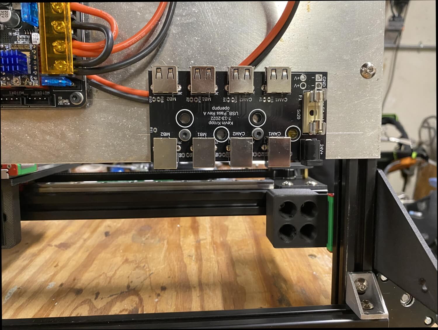
I made some simple connector boards so the back of the pick and place will have USB A ports for connecting the 2 cameras and USB for the main board.
I wanted this to be able to be thin enough to put up on a shelf and pull down when ever I need to run a board and the overall height was a big focus
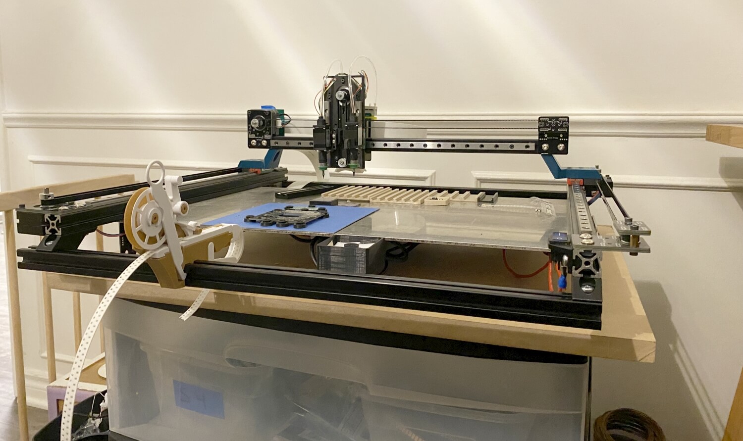
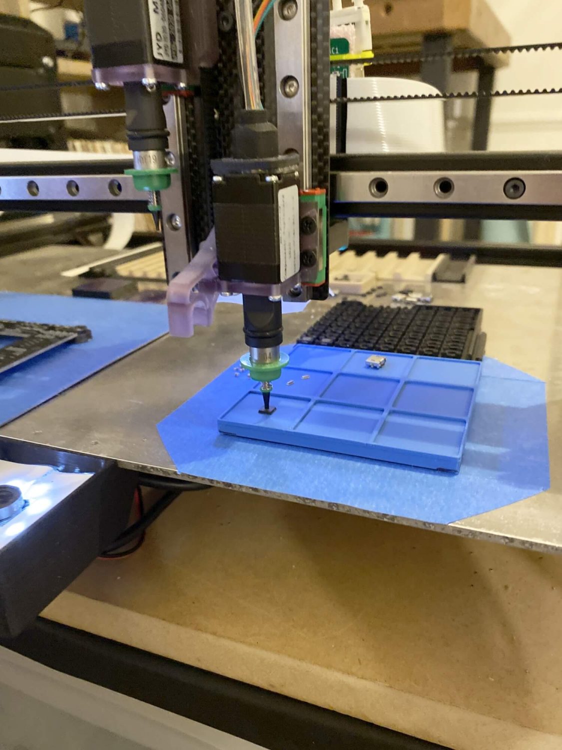
Instead of housing the whole device in a box I added a plate to the x gantry to provide a consistent backdrop whenever the up facing camera is used.
The vacuum pumps, one for each nozzle are mounded on the head with a short piece of tubing looping over the head to the nozzle adapter.
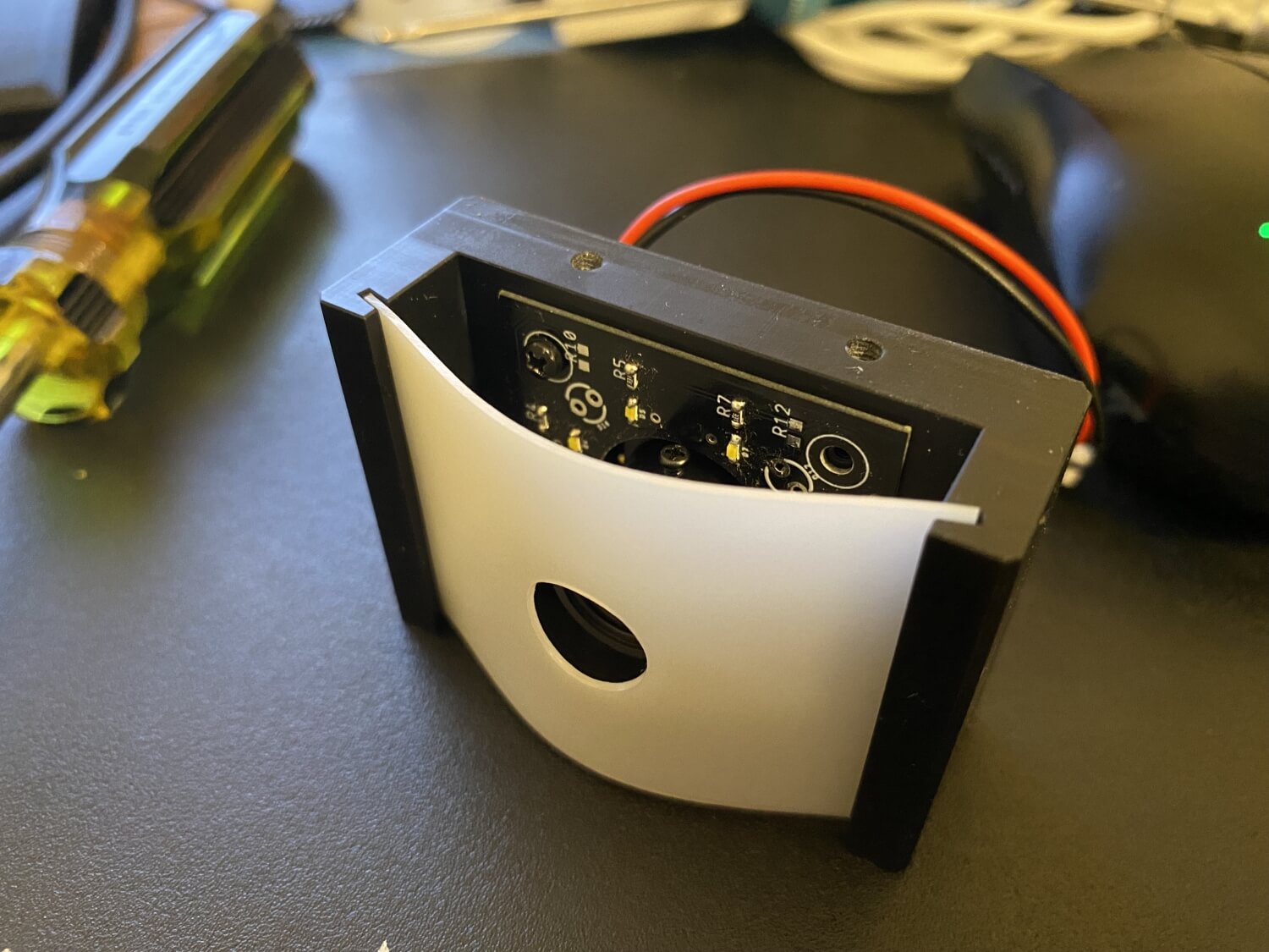
I originally did not put much effort into cameras or lighting but as soon as I tried to use basic strip feeders I had recognition issues and stared to look at light diffusion and reduced reflection. I also ended up making a ring light so I could control the brightness.
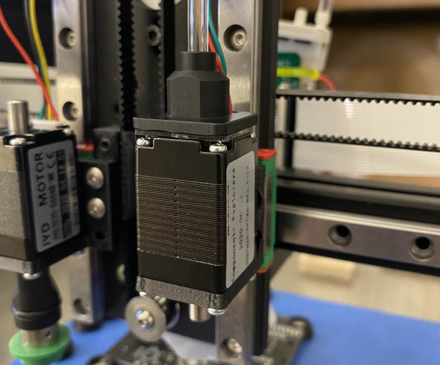
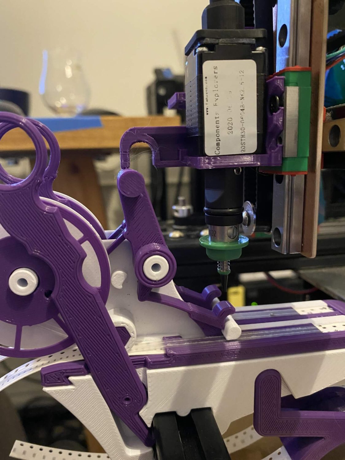
With keeping the height as low as possible, the typical swivel fittings for the nozzle motors added upwards of 30mm so I tried to seal a plastic fitting to the motor with double side tape to create essentially a small vacuum chamber that would allow the motor shaft to spin freely. this works great and would even allow for the shaft to be flush with the motor and reduce the height even more but isn’t needed, yet.
changes I would make if I could go back:
-I would not have the up camera mounted on the front rail as it takes up feeder space
-I would opt for an easier camera lighting solution like an enclosure for consistent camera lighting
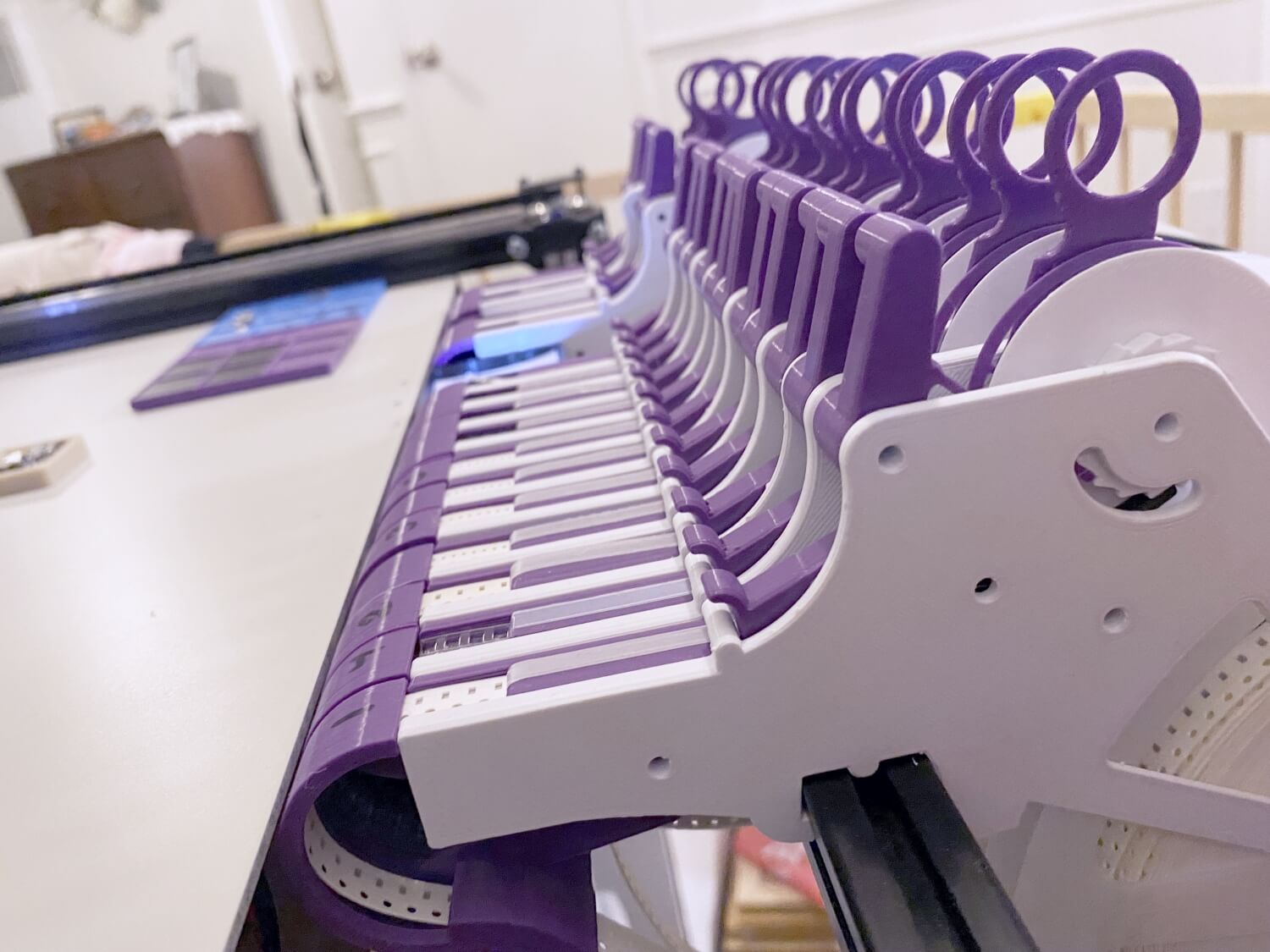
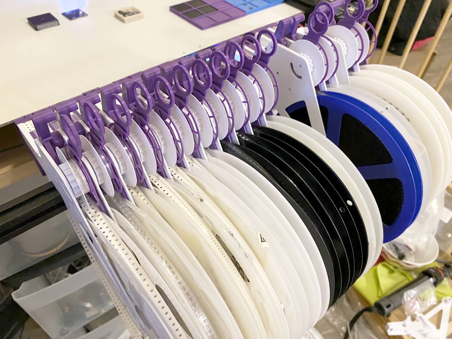
-I would go with a drag feeder as the feeders are just so much work- I might still do this anyway and not finish my feeder design, the only thing that needs to be done is the cheep feeder design needs an adjustable friction control system to hold the tape and pull the clear cover.
Nozzle tool changes looks fun to do but probably not necessary
I will make another update about feeders and the options.