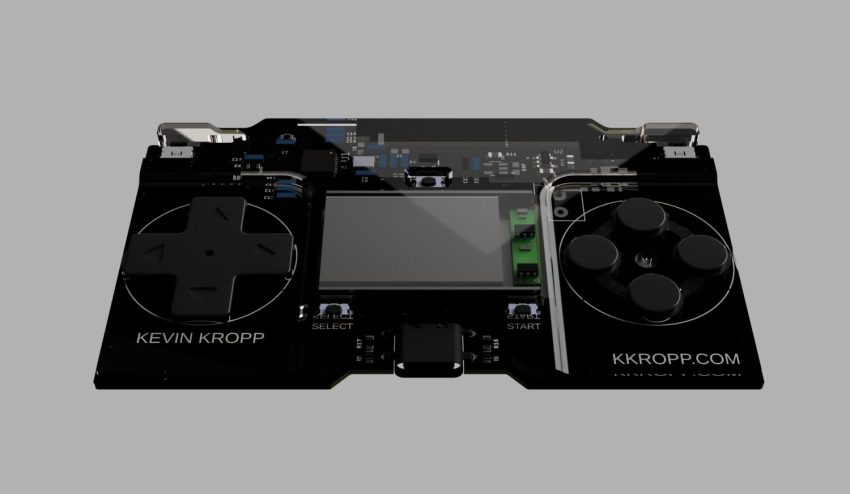
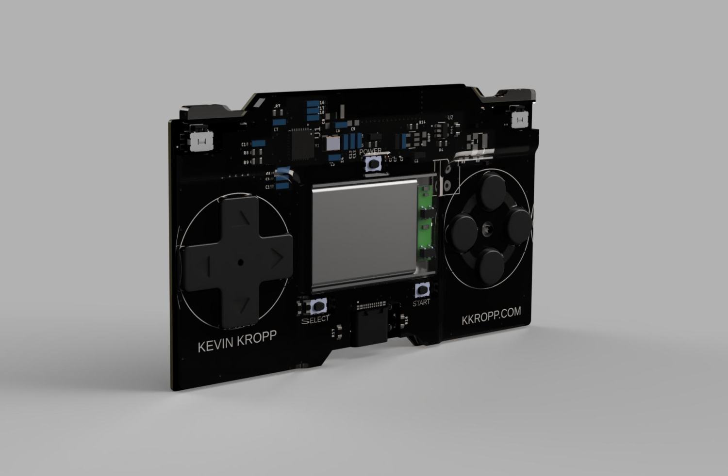
I wanted a simple Gamepad to play retrogames on a phone that I could have with me all the time. It is small enough to fit in a wallet and has a 150mah 302030 battery that will last for about 3 hours. overall dimensions are 86mm x 50.8mm x 4mm. There is a D-pad, 4 buttons on the right, 2 bumpers, start select, and a power button.
REV2 7-21-26
Major rev changes:
-Migrate to C6 for more GPIO
-Added BMS directly to board
-Added L2, R2
-Added battery level indication and player select via 4 RGB leds
-Added BLE status led
-Implemented light sleep to bring battery life from 2h to 12h
-Added power button as a usable button
-On the go button mapping via wifi ap webpage
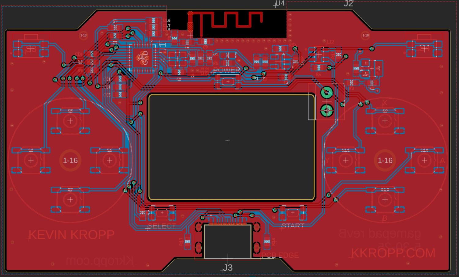
-Moved from a tray for the battery to machined pocket in the PCB
Minor changes:
-Improved antenna trace design
-Rotated dpad and buttons
-Used smaller L1 R1 buttons with pins
-Added sot23 parts for front plate adhesion
-Moved to thin buttons for start and select
-Moved to smaller package for crystal
-Made battery pocket larger
One of the hardest parts was finding IC and stack that would work with IOS. Android is pretty compatible with most hardware and devices requesting Bluetooth pairing. The nimble stack for the esp family has support for the S3 and C3. I did end up using the C3 and have a few issues with the hardware mostly related to the recommended chip variants removing support for one of the GPIO banks and therefor needing to remove some features live battery voltage reading (more on this at the bottom of the page).
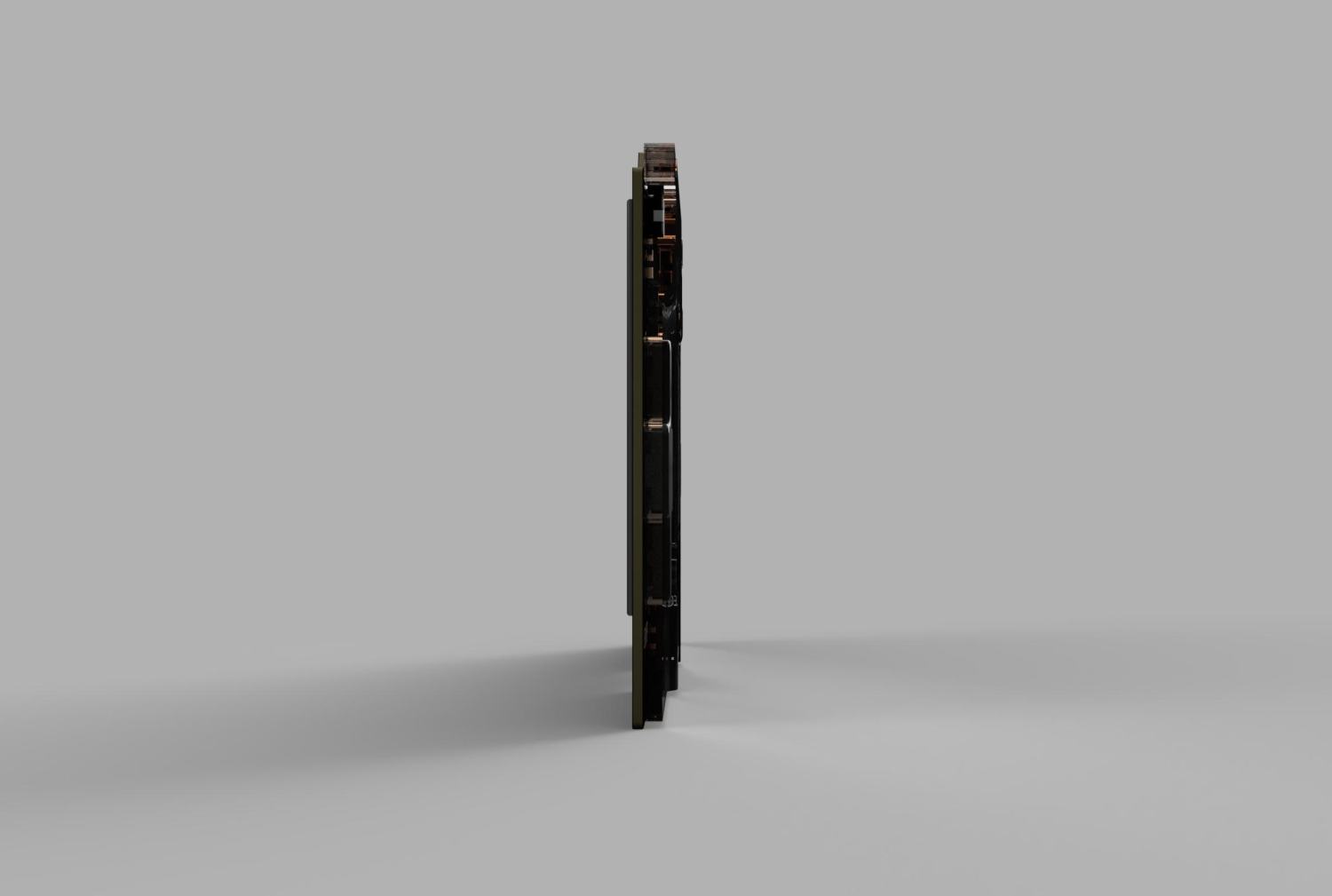
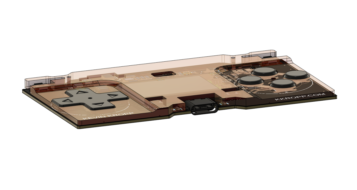
One of the main engineering goals was to make it as thin as possible. at the moment is has a 3mm thick battery that fits in a cutout in the pcb. there is then a plate on the back .5mm thick and a polycarbonate faceplate that covers the front of the battery with .5mm the faceplate drops down around the buttons to give them 1mm of reveal to not increase the overall profile.
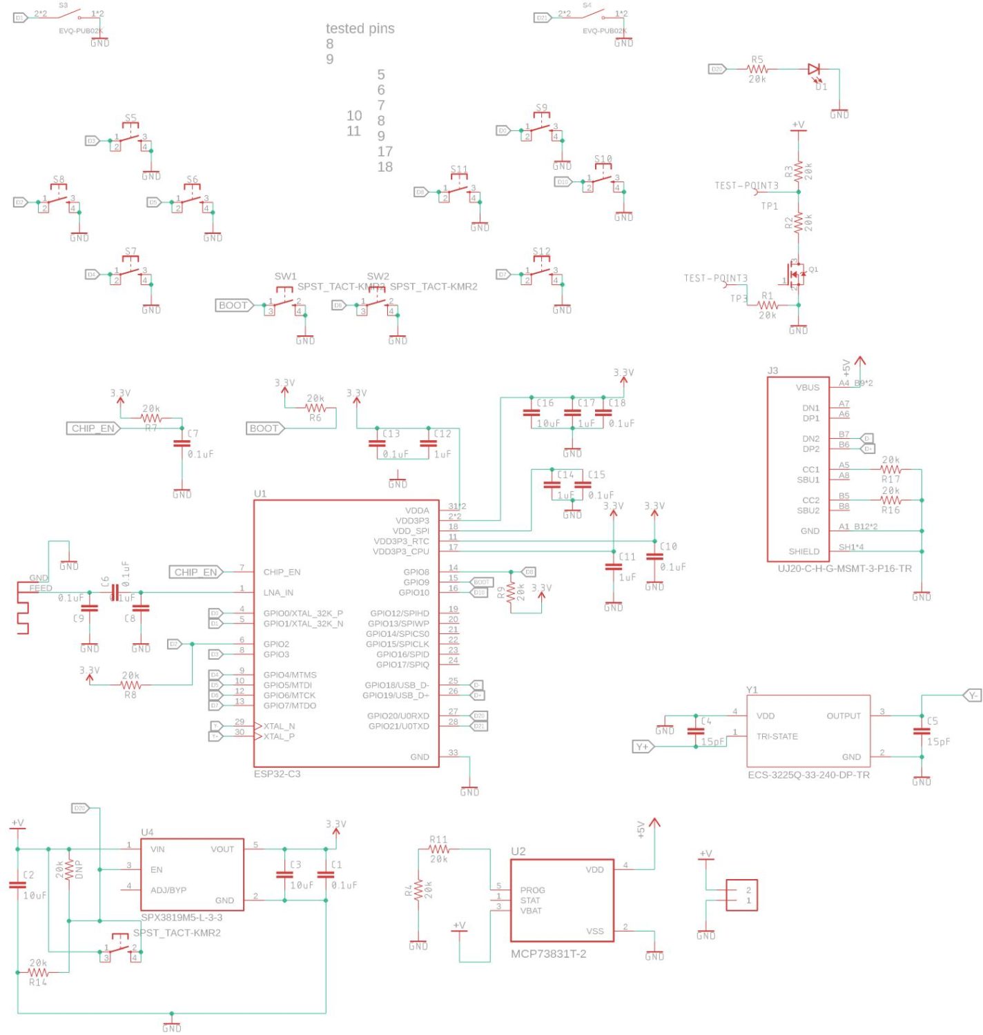
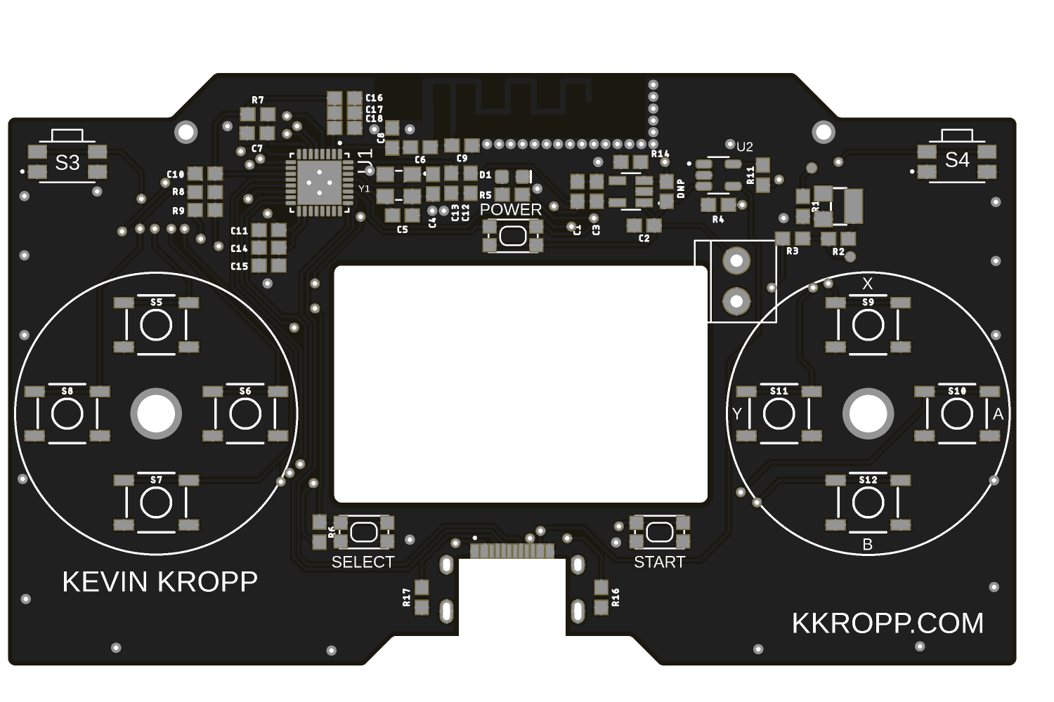
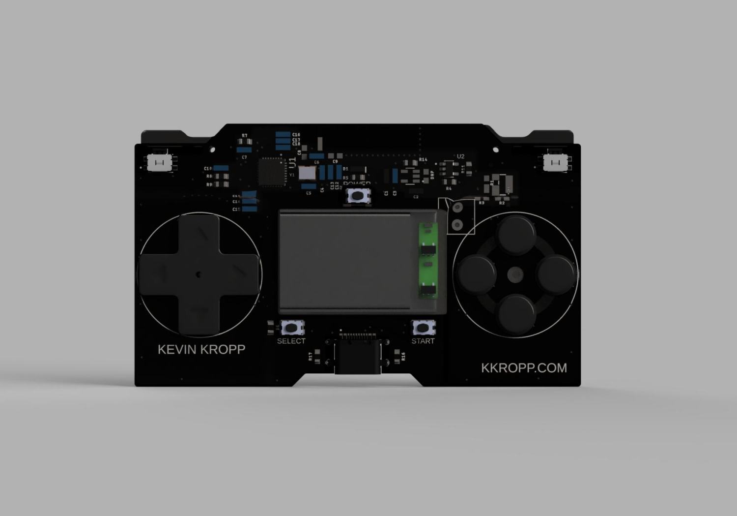
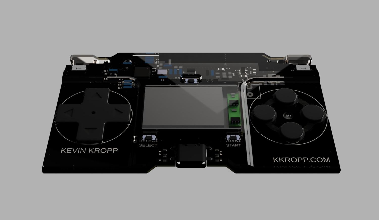
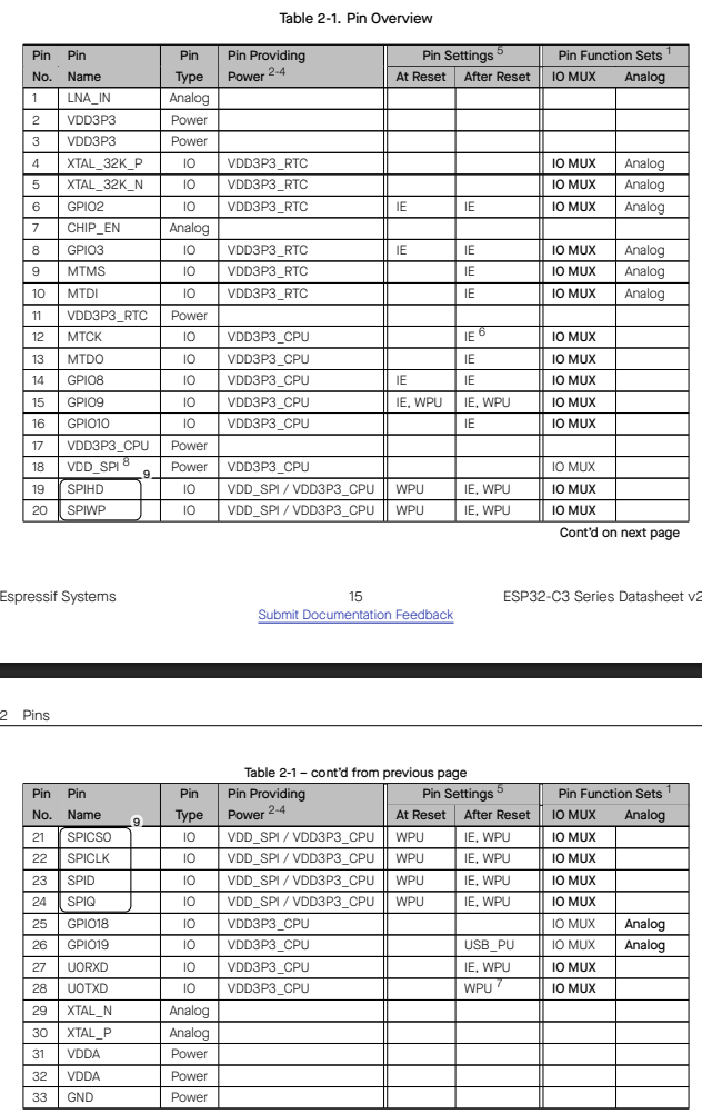
There are 5 versions of the esp32 c3 qfn32 1 of witch is end of life
2 of the packages provide 22 GPIOs with pins 19-24 acting as GPIOs these are the c3 n4 and h4
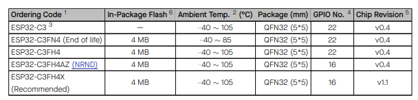
The base esp32c3 is still revision v0.4 and the recommended is the x variant and is likely going to be the IC available moving forward
With that in mind the 16 (actually 15) GPIOs to use are
0
1
2
3
4
5
6
7
8 – This is the boot pin so it should not be held while booting for normal use
9 – This is a boot pin
10
11 – pin 18 but is normally configured as power in and not natively setup to be a gpio
18 – used for usb
19 – used for usb
20
21
A good test would be to see if 18 and 19 could be used as long as usb cnc on boot is disabled (and would hurt debug a lot but might be ok for production)